 |
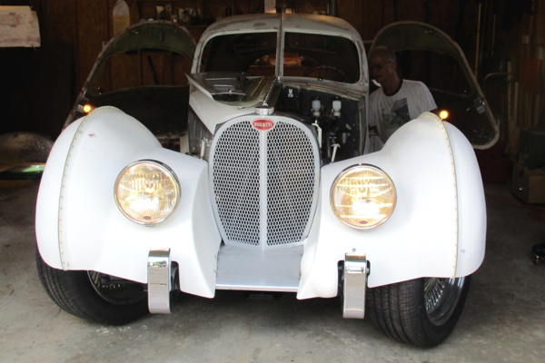
1936 Bugatti Atlantic Replica Project |
harness/wiring, and fixing mistakes that we'll call "Systems / Wiring", and see where it goes...
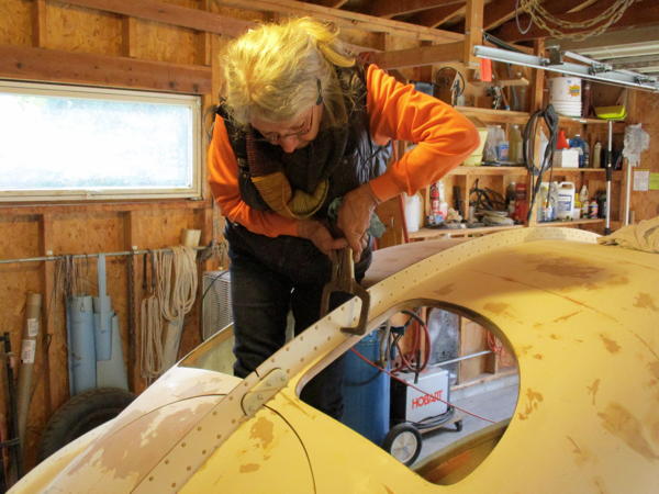
[10-12-15] Gluing in the heads of the important characteristic Atlantic seam rivets...
Including the 64 hood 'rivets' (which are actually #6 screws), there are 818 rivet heads in the RABUGGI flanges.
(Rivet cutter to cut 5/32 AN rivets to 0.080 long - drawing)
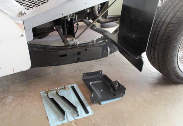
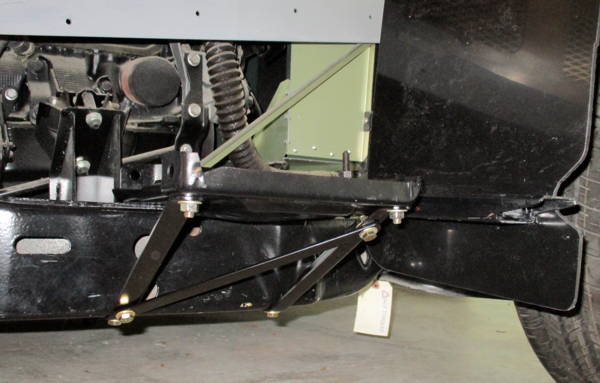
[11-07-15] The S10 battery tray, braces
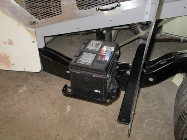
[11-07-15] Battery tray will be inside right front fender behind splash shield.
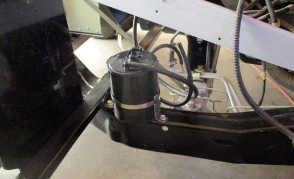
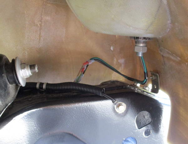
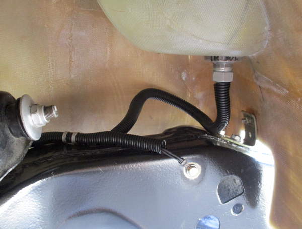
[11-09-15] The S10 fuel vapor canister mount, under left front fender behind splash shield
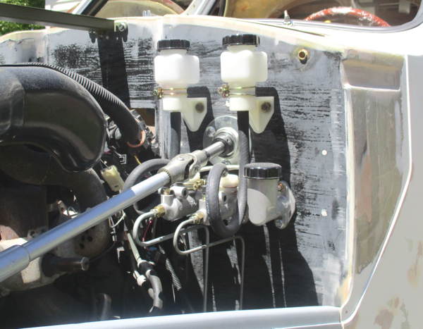
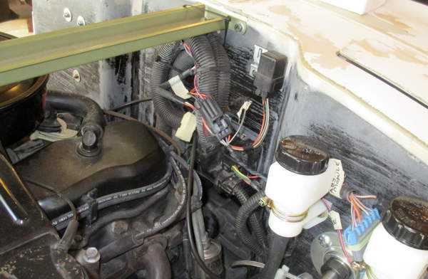
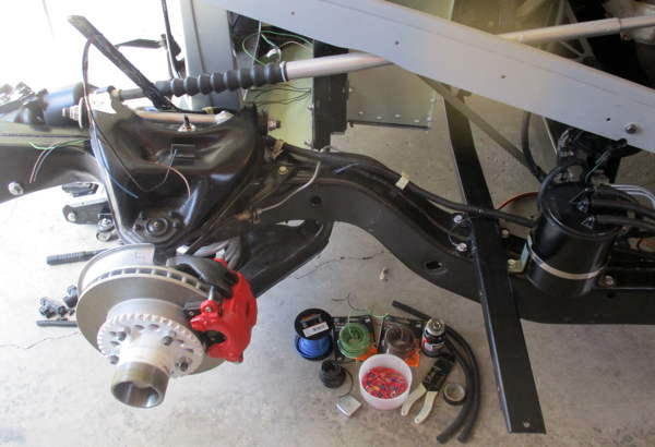
[06-08-16] Wilwood brake / clutch master cylinders & remote reservoirs...
Clutch is 3/4" dia. Front is 13/16", rear is 7/8", fitted as a pair with a balance bar.
It gets a little crowded in here but it all fits and everything is accessible.
Here's a brake / clutch "plumbing plan" diagram.
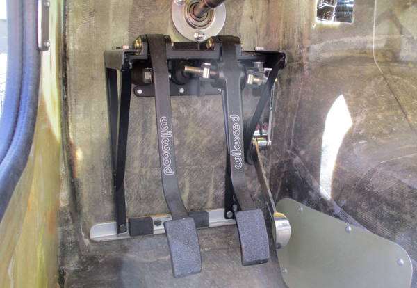
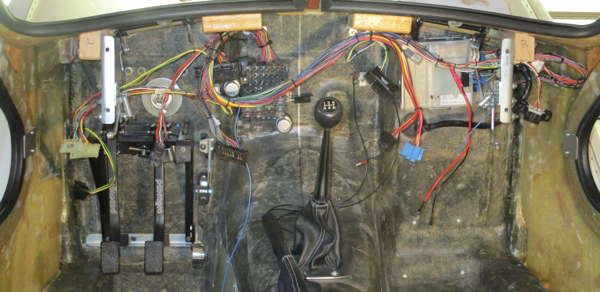
[06-08-16] Wilwood brake / clutch pedals assembly and speedwaymotors.com spoon throttle pedal...
Wilwood cylinders & pedals from Summitracing.com or Speedwaymotors.com.
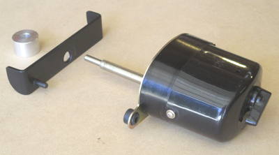
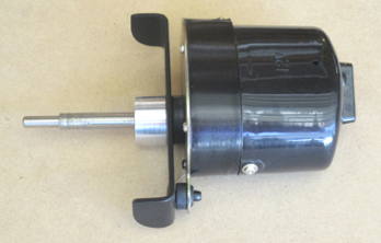
[06-08-16] Windshield wiper motor torque reaction brackets...
These 12v, single speed, 90 deg. sweep, integral switch units are from Speedwaymotors.com.
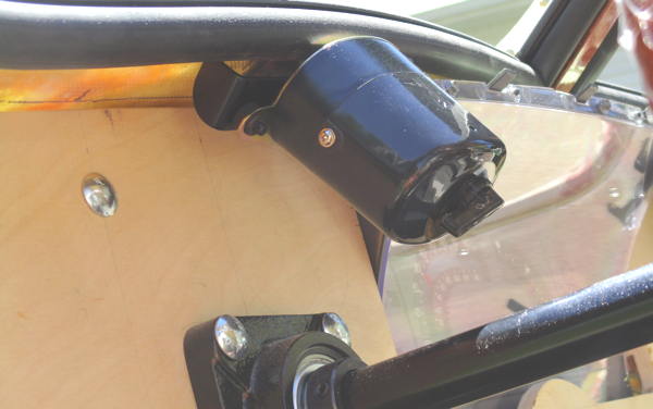
[06-08-16] Windshield wiper motor mounted with torque reaction bracket
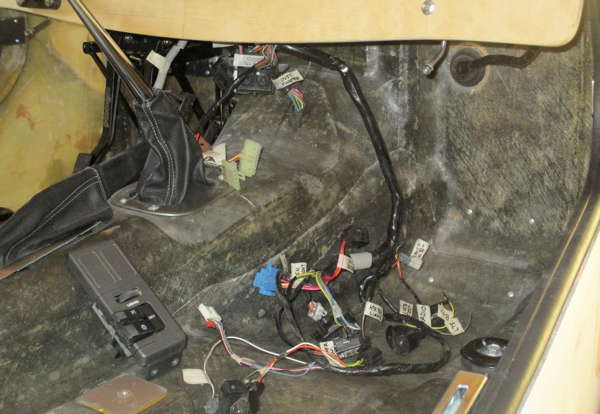
[06-20-16] Beginning of sorting, adapting, fitting the donor S10 wiring harnesses - hmmm - not pretty
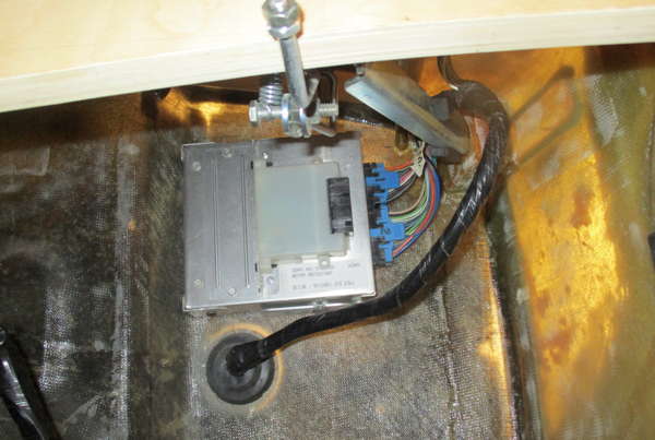
[06-20-16] The donor S10 ECM and DRAC module mounted on right firewall
[06-30-16] Firewall connector from donor S10...
WIRES! -- This job is not very glamorous, but needs to be tackled.
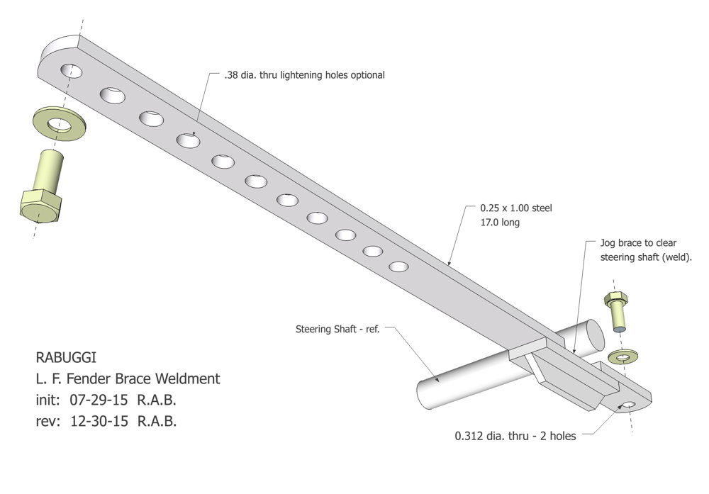
[06-30-16] stringing wires to front lights, extending, securing, covering...
The L.F. fender-to-frame brace (visible upper left) is this weldment.
[06-30-16] Right side headlight spade connectors
[06-30-16] Right side headlight wires, dressed with split-loom
[06-30-16] Right side parking / turn light bullet connectors
[06-30-16] Right side parking / turn light wires, dressed with split-loom
[06-30-16] Right side bullet park / turn light on top of the fender, in the spirit of Atlantic #57374
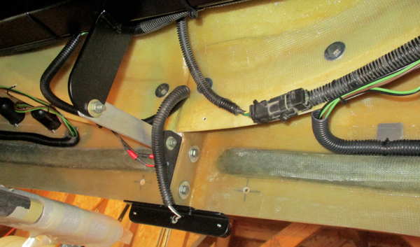
[07-09-16] Adapting the donor S10 rear wiring harness
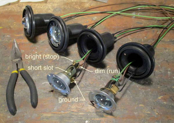
[07-09-16] Wires and bullet connectors for the Lucas 488 tail/brake/turn lights
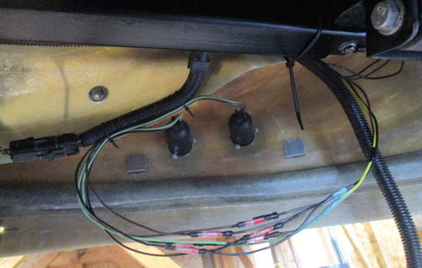
[07-11-16] Bullet connectors for tail / stop lights harness
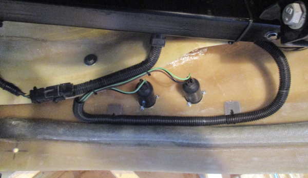
[07-11-16] Tail light harness, dressed
[07-11-16] License and backup lights harness, dressed
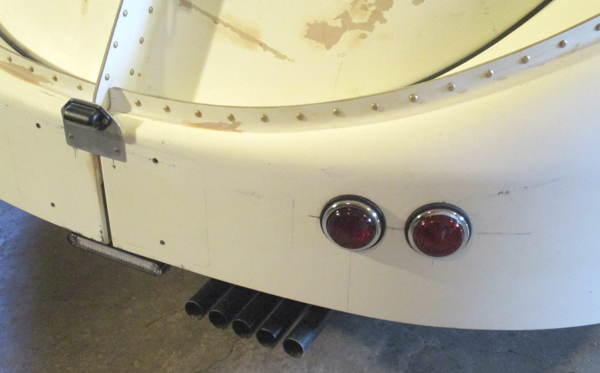
[07-19-16] The Lucas 488 tail / stop / turn lights look pretty correct.
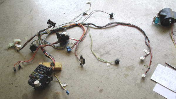
[07-19-16] On to the donor S10 under dash panel harness...
Ugh! We need to adapt this mess to our panel and switch layout.
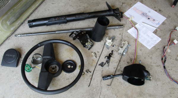
[07-19-16] Donor S10 steering column & switches...
Retrieve and adapt the turn / flasher, headlight dimmer, and ignition switches.
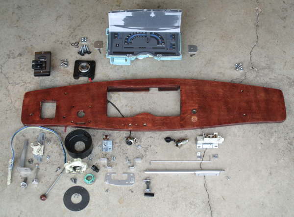
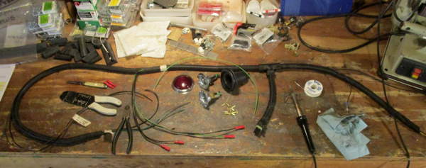
[08-20-16] Family portrait of all the switches, adapters, and parts from the last month or so...
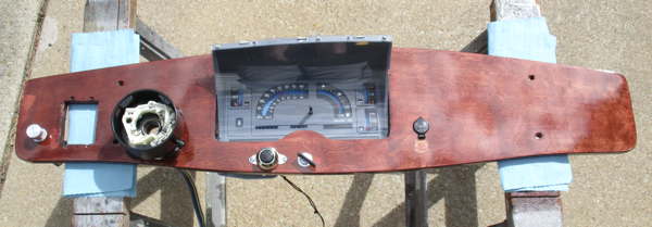
The birch panel stained mahogany looks about right, but has some visible defects and may be done over.
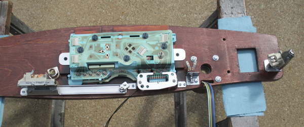
[08-21-16] Dash panel assembled with most of the adapted S10 parts & switches...
eg: dimmer switch, ignition switch
[08-21-16] Under cowl harness dressed and ready for plugging in to the assembled dash panel
[08-24-16] Dash panel, switches, cluster, installed and connected
[08-24-16] First electrical checks -- lights-on!
[09-05-16] First Engine Start-up...
This is kind of a big deal after a week of frustration with some stuff not working right.
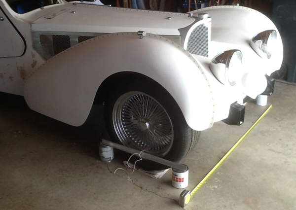
[09-12-16] Quick & dirty toe-in check...
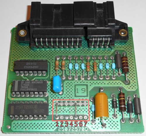
[01-20-17] The donor '91 S10 DRAC board with O.E. jumper configuration (1000100)
|
Recalling from the Wheels/Tires page, RABUGGI's 235/50 R18 tires are nearly 5% larger in rolling radius than the OE 195/75 R14 tires of the '91 S10 donor. This would make the speedometer read 5% LOW, ie: at an indicated 55 mph, we would be actually going 58 mph. However, the G.M. DRAC (Digital Ratio Adapter Controller) can be recalibrated by adding/deleting some jumper wires on its circuit board. This site, VSSB DRAC Calibration, appears to be a credble reference for the Input Ratio /Jumper scheme for executing this recalibration.
The above site's calculator is doing this calculation
for an "Input Ratio", a function of the axle ratio and measured tire rolling circumference (in/rev). The jumper settings can then be read from a provided look-up table (of uncited origin). |
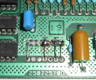
[01-21-17] The '91 S10 DRAC board with the recalibration jumper configuration (1001011)...
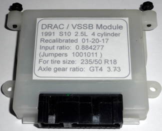
DRAC case with a recalibration iinformation label...
We can verify the speedometer against a GPS when decent weather returns to Wisconsin.
| In the context of speed and speedometer, we'll add this little RPM calculator, a function of tire rolling circumference, gear ratios and vehicle speed. Default values are RABUGGI's (with the '91 S10 donor's T-5 MW1 transmission and GT4 3.73 axle). |
 |
[02-25-18] Graph from a spreadsheet for calculating the HP required for a given vehicle speed... [Download the .xls file if you like.]
So, for those who want to know, we can say that RABUGGI's top speed, with his little LN8 94 HP 2.5L four cylinder (left),
is about 106 MPH -- without going out and doing something dangerous, illegal, and stupid to find out.
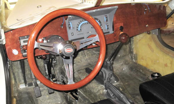
Post completion upgrade... Horn Button in Wheel
|
During the initial wiring work it was decided that putting the horn button conventionally in the center of the steering wheel would be too difficult, so a pushbutton was simply mounted on the panel. Although functional, this was an awkward reach to use. So now that there's more time for “difficult”, a scheme for the required slip-ring and contacts to handle the moving (rotating) electrical grounding circuit is addressed. (The old saying applies: “There’s never enough time to do it right, but there’s aways time to do it over”).
Drawing [.PDF] of the scheme for wiring the horn button grounding circuit into the steering shaft... |
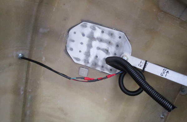
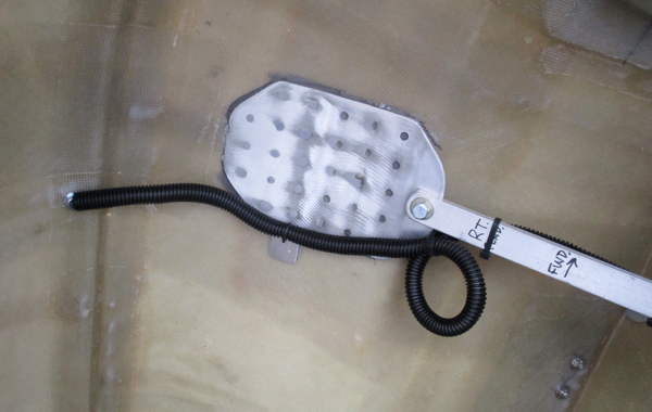
[11-24-20] PVC insulating sleeve, copper coupler slip-ring with 18 ga. wire soldered through hole in end...
[11-24-20] Sleeve, slip-ring with wire epoxied in place on forward end of steering shaft...
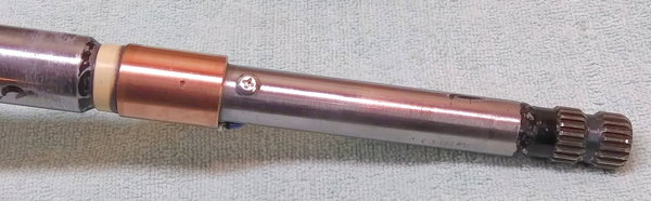
[11-25-20] A #6 screw in shaft protects the slip-ring wire from being jammed into bearing during assembly.
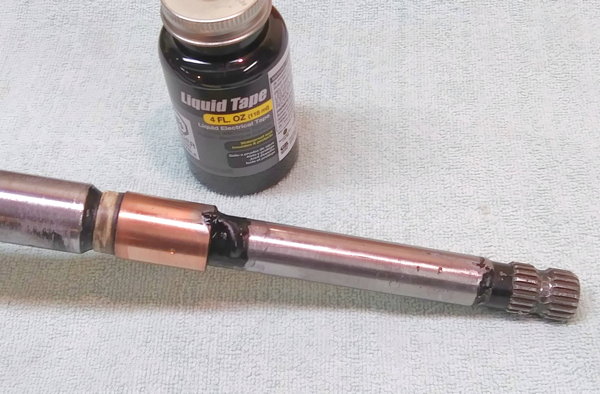
[11-25-20] 18 ga. wire has been pushed up the shaft to the wheel end.
Liquid Tape will secure and protect the exposed wire end.
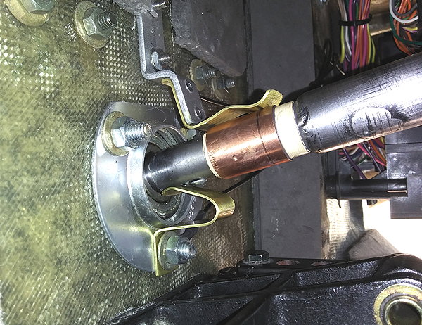
[11-28-20] View inside firewall of steering shaft, bearing, and the new contact wipers and slip-ring...
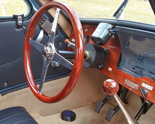
[11-28-20] Horn button in center of wheel... Form factor is in the spirit of a Type 57.
Post completion upgrade... Throttle Pedal Bushing
|
The purchased Speedway Motors spoon throttle pedal is a good fit (with modification) for our application. Although functional and smart looking, its original plastic bushings had excessive diametrical clearance in the ID (about 0.020 in), resulting in a loose pivot that just didn't have a "quality feel" to it.
Serendipitous surprise!... A local hardware store had a metric bronze flanged bushing that was a perfect replacement for those sloppy bushings, with minimal scraping and fitting. |
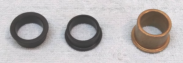
[11-27-20] Original plastic (black) bushings and replacement sintered bronze bushing...
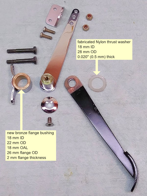
[11-28-20] Throttle pedal parts showing the new bronze flange bushing and a Nylon thrust washer...
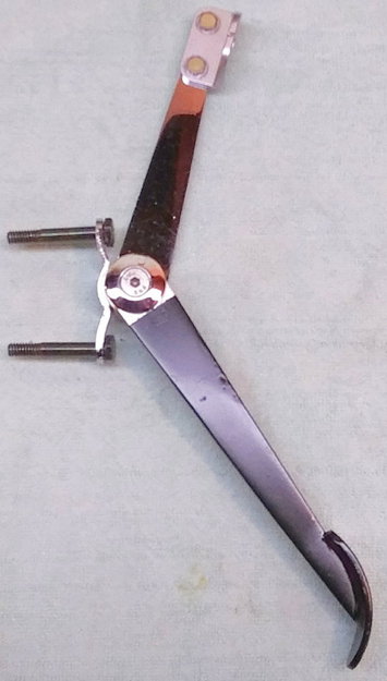
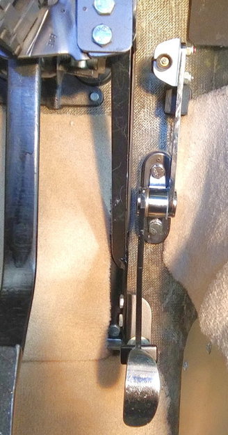
[11-28-20] Left: Throttle pedal assembly complete... Right: Throttle pedal assembly installed back in Rabuggi...
Operating motion is now much more precise feeling.
Post completion upgrade... Battery Quick-Disconnect Switch
| Accessing the battery location behind the right front wheel is not a difficult task (C-4 Corvettes come to mind as worse), but is indeed slower than just popping the hood if you need to get at it quickly. A quick-disconnect battery cut-out switch seemed like a good idea in case of a situation like a stuck starter solenoid, as well as a convenience when doing electrical system work. |
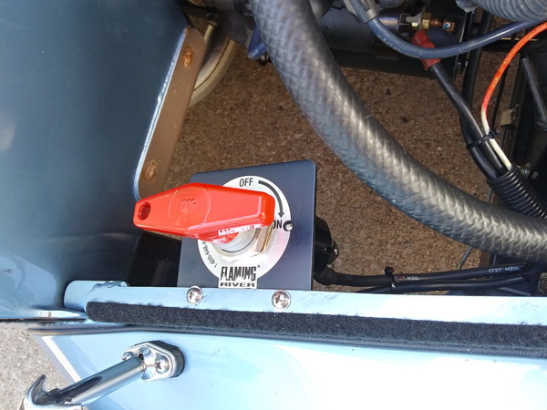
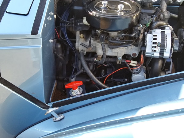
[10-04-21] The Flaming River FR1003 "Big Switch" looks like a sturdy, well made, waterproof unit.
Here's our installation...
Post completion upgrade... Sealed Beam Headlight Adaptor
|
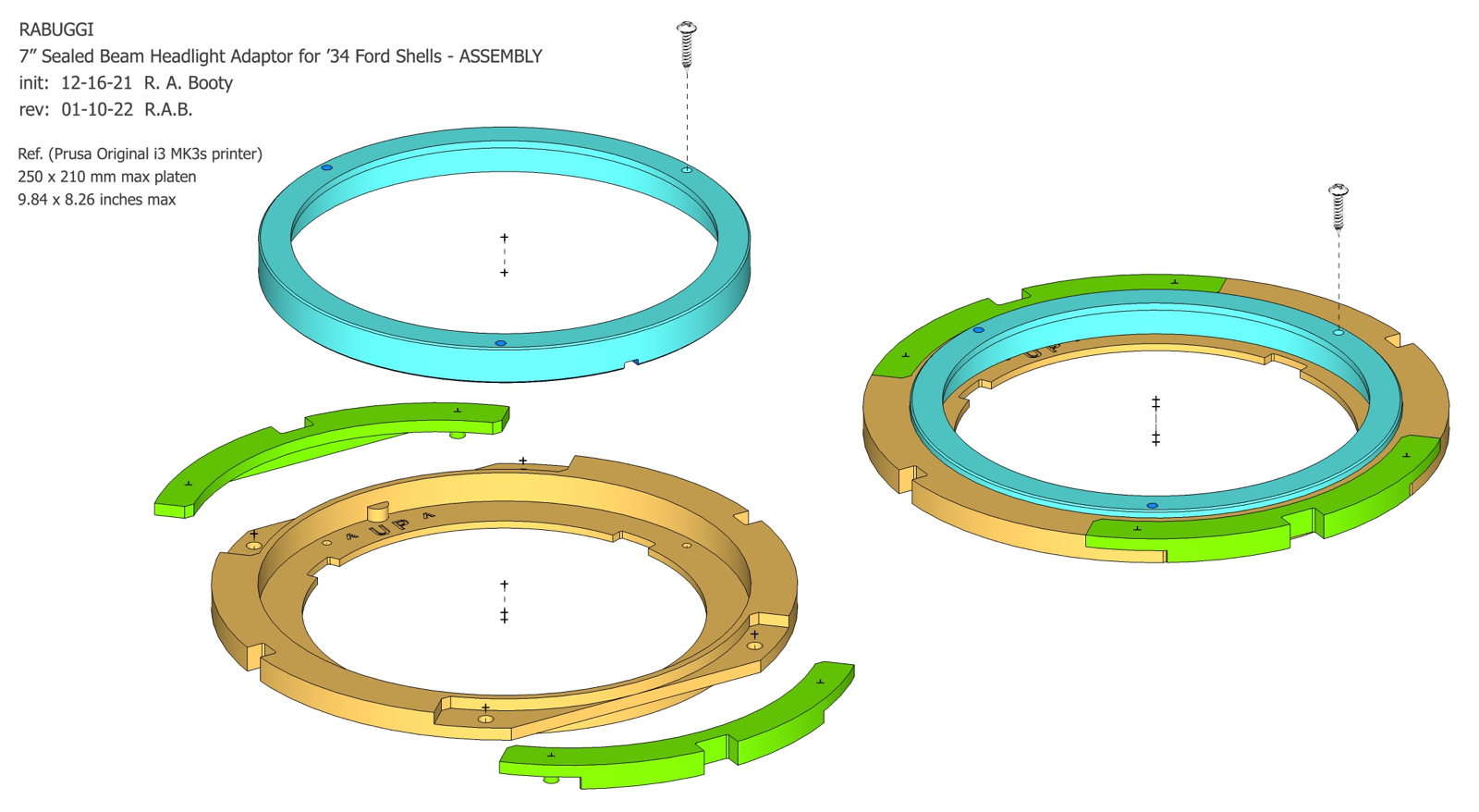
After continually experiencing disappointment in the '34 Ford lights effectiveness on back roads at night, I bought and mounted some Dietz style lights (7 in. Halogen bulbs). They were OK, but lacked the “grand” (and very correct) appearance of those big old 9.25 in. shells. Making some adaptors to fit H6024 bulbs in the Ford shells should be an achievable and reliable improvement.
A retired engineer friend recently bought his own Prusa 3D printer, and uses SolidWorks CAD software to design and print all kinds of cool "stuff". We discovered that I can export an .STL file for a part modeled in my SketchUp 3D program (not as powerful as SolidWorks, but I have experience with it) and attach the .STL in an e-mail to Chuck (across town). He can then slice it and print a part in PETG plastic material. ...Much less labor and material than buying chunks of aluminum and making a lot of chips with the lathe! [Here's a 2D .JPG export of the SketchUp model of the sealed beam adaptor assembly.] |
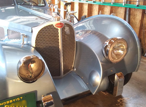
[01-14-22] A preliminary fit-up (driver’s side) of the adaptor assembly,
and a Dietz shell (passenger side) with the H6024 bulb robbed out of it....
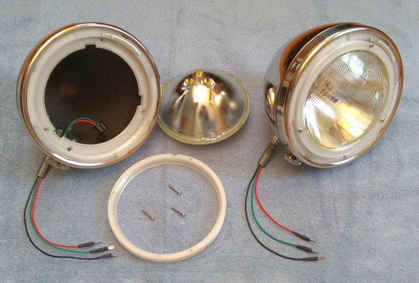
[01-27-22] Complete assemblies ready to go out to the garage when it gets up to 50F or so...
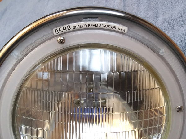
[01-27-22] Close-up of adaptor with a label to maybe trick the observer to
think that yeah, this is a period correct aftermarket conversion... :-0
 Addendum to Headlight Saga... LED Upgrade
|
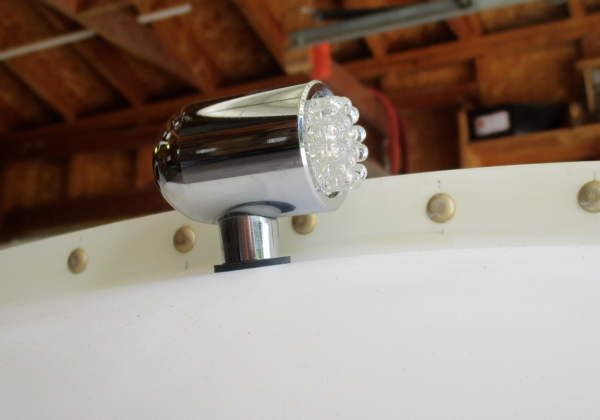
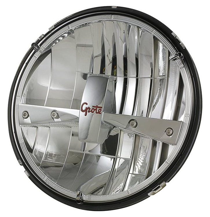
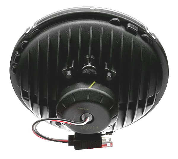
The pair of H6024 lamps (above) were performing just fine, but melted high/low beam selector switches in about 6 months. Rather than a re-wire upgrade to the system, I elected to order (from Summit Racing) some modern LED units which have brighter useful illumination, more precisely defined pattern, all at HALF of the current draw (!!) of the H6204 halogen units.
The selected lamps have a quality look and feel. They fit easily into our custom sealed-beam adaptor rings (above) which were designed to SAE J1383 APR85, so it's credible that these lights comply with the SAE/DOT (street legal) claim. The first drive at night after installing and properly aiming these lights was an "Oh, wow!" experience. (Observation: These Grote Industries 90941-5, and the Anzo USA 881035, are SAME AS United Pacific 31400 except for the brand labeling.) |
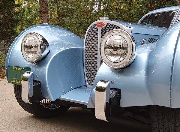
[10-10-23] Grote 90941-5 LED sealed-beam replacement headlights installed in RABUGGI
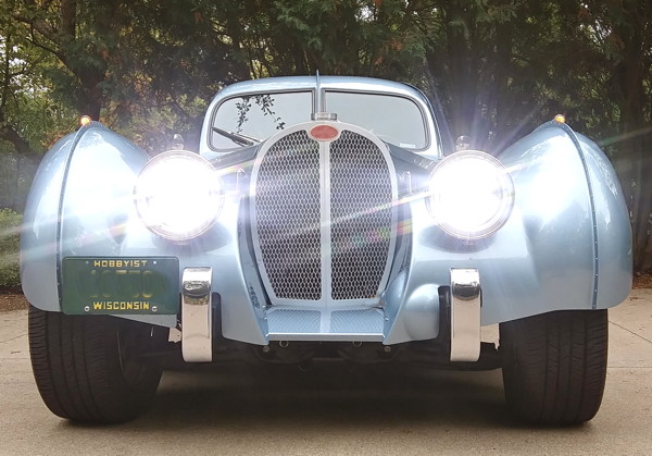
[10-10-23] Grote 90941-5 LED sealed-beam replacement headlights -- LIGHTS ON!
Relevant files from the project archive of misc. drawings, notes, and data:
|
Post completion upgrade... CHMSL add-on
|
[ Center High-Mounted Stop Lamp ]
An episode last spring of very nearly being rear-ended while slowing for a left turn stimulated initiative for this add-on feature. It's obviously NOT correct for a "1936" car, but I think I'll feel safer driving in traffic. |
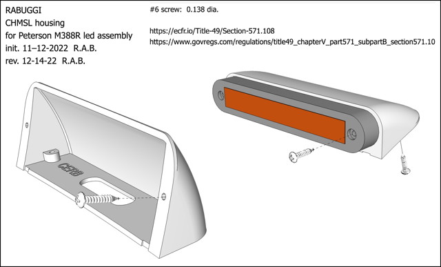
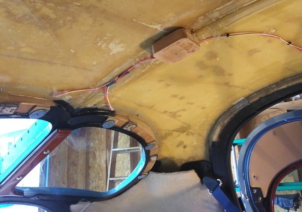
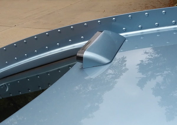
[12-14-22] Two mounting housings are 3D printed in PETG, painted to match the '64 GM Silver-Blue.
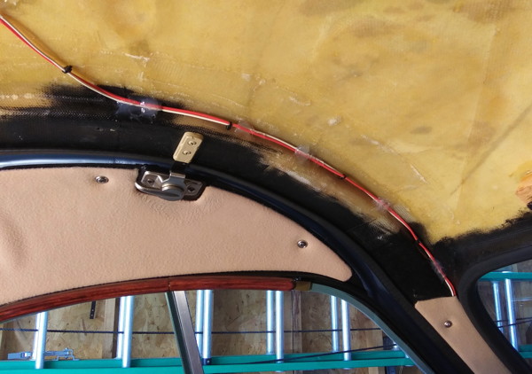
[03-24-23] 18 ga wires run up the 'A' pillar, back across the roof, and will be hidden by trim strip and headliner.
(ref: Lights Wiring Connection Notes - .PDF)
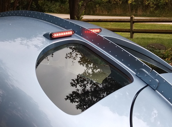
[03-24-23] BRAKES ON!... The red LED light assemblies are Peterson M388R.
| -- Site Navigation -- [Website Disclaimer] (pop-up) [Site Map / Search] | ||||
|---|---|---|---|---|
| 57SC Home | Donor/Chassis | Wheels/Tires | Body Patterns | Body Molds |
| Body Pieces | Hood/Radiator | Systems/Wiring | Interior Details | Glass/Finishing |
![]() Last tinkered with May 19, 2024
Last tinkered with May 19, 2024